Still no Sweep
I have to admit that I was hoping that if I fixed the -8V line then the scope would jump into life and everything would work. Alas not.
The trick was where to begin as I know there is a problem with triggering as well as sweep. I decided that even if I can't trigger but I can get sweep happening (in auto mode), then I could move forward. Also, the troublshooting flowchart in the manual suggested I should look at the sweep first.
The sweep circuits in the oscilloscope are quite complicated. There are actually two separate sweep generators that can run at different rates. You can set the scope up so that the 'B' sweep starts a short (and configurable) time delay after the 'A' sweep starts. The cool thing is you can run the 'B' sweep at a faster rate which allows you to effectively zoom in on part of the signal. You can move around the longer trace by altering the delay. Then there is 'A' intensified by 'B' mode, Mix mode and... well I don't know.
The next problem is I've never used this scope - well not in a working state so it took a bit of googling and youtube watching to actually figure out what it is *supposed* to do. For example the time/div knob is marked 'A and B TIME/DIV' and the end of the knob says 'pull' but I didn't see how this worked. It was hard to pull and nothing seemed to happen (I expected it to pull out and click). I turned out you have to pull the knob and then turn it. If you do this it disengages the grey knob from the clear skirt and allows you to set the A and B sweep rates to different values. When you rotate either back so they are on the same speed then they lock together and then when you rotate the knob they both turn.
Sweep Generator
The sweep generator is pretty complicated. The first thing that puzzled me was the the differential amplifiers (Q914, Q926 and so on). To begin with I decided to keep it simple and went looking for a sweep signal coming out of Q956. Sure enough there was nothing there (just a constant 15V). But the sweep circuit is initiated by the 'gate' signal from the sweep logic board. The 'A' sweep seems to get initiated by the main sweep gate coming in on the base of Q902. Looking at TP902 I can see the amplified pulse coming in. Great! That means the fault is somewhere in here... Somewhere anyway...
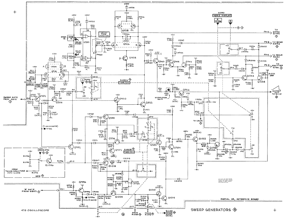
I noticed that if I turn the sweep rate right up to one of the top three speeds (shortest time per division) that I get a short (about half screen) trace on the scope. I scoped the sweep output while this was happening and sure enough I could see a 'V' which was the sweep reducing the output voltage in a roughly linear ramp.
I still didn't get how this all worked. I knew from the manual it was a 'miller integrator'. Turns out this is pretty simply just an amplifier with a feedback capacitor. The capacitor charges roughly linearly and provides the output ramp. The capacitor/resistor used to determine the time constant are switched in by the timing board depending on where you rotate the time/div knob.
Digging a bit deeper I see that the transistors facing up the page like Q904 are configured to either pass or block the gate signal going to one bit of the circuit. The circuit description in the service manual describes these as a 'disconnect amplifier'. So each sweep generator is a JFET and a transistor together with a variable resistor/capacitor from the timing board. They also have a disconnect transistor that turns that sweep on or off depending on what switches you pressed.
So I choose 'A' mode on the scope and looked at the signal coming out of Q904. I found that it was a bit feeble and scratched my head about why. I figured out the A (lock knobs) button puts 5V to the diode going to the base. I fiddled with the time/div knob and figured out the pulse starts to look like a feeble 1V ramp if I set the time/div to one of the middle speed settings! Ok there is some life in there.
I noticed the voltage at R921 was around 14V. I thought perhaps the capacitor C922 had shorted so I lifted one of its legs but it appeared fine. In fact the circuit was the same without it.
I noticed there was a 1V ramp happening on the collector of Q922 so I followed this through. At the emitter of Q940 is was a feeble bump rather than a ramp. I guessed Q940 might be suspect and pulled it. The transistor tester didn't even identify it as a transistor so I replaced it with a BC547 and tested again. This time the ramp looks a tiny bit better but still no output from Q940.
The trouble is I don't know what it is supposed to look like. I remembered the fast sweep sort-of works so I switch into the fastest sweep rate and looked at the collector of Q1014. The first thing I noticed was the ramp was starting at 15V and going down instead of the feeble 1V. The emitter of Q1022 also showed this ramp.
The voltage at R1011 swung a lot more. This made me wonder if the JFET Q920 might be toast. On a whim I decided to swap the JFET from Q1010 and Q920 to see what would happen and Voila! The medium/slow sweep now works!
I tried putting Q940 back but no that didn't work. So I had two faults - Q940 was dead and one JFET. The JFETs are a bit unusual so I will have to order some from the US.
I did some more investigation and B sweep is dead as well as the fast sweep. Trigger is still broken and there seems to be some problems in the front-end. I can get some wave form if I wiggle the volts/div channel 2 knob but nothing on channel 1.
So more work to do but some progress!
.JPG)
No comments:
Post a Comment