Transformer Winding
So I needed an additional winding so that I could get a voltage a few volts above the bulk capacitor in order to drive the MOSFET gate. I tried a voltage doubler but this messed with the AC waveform enough that it meant the pre-regulator zero crossing detection didn't work.
The plan was simple - I wrapped a few turns of insulated wire around the transformer, attached the ends to a multimeter and turned the transformer on (being careful not to short the outputs as that would be bad!). I calculated I needed to add 40 turns to get 10V. In the end I only got 8V but it doesn't matter.
I bought some 1.2mm (18AWG) magnet wire from Jaycar which is way more than I need as the current required from this winding should be minimal. I got a bolt from the shed and put this into the chuck of a battery drill. I wrapped a couple of turns on the bolt (particularly the square head bit) to get the wire attached. I wrapped a cloth around the wire so I could hold it and turned the drill on slowly. Every so often I squashed the wire together. I put the whole real onto the bolt (as I didn't want to run out!)
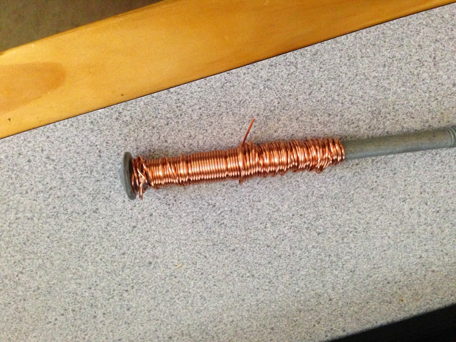
I fed the bolt through the centre of the transformer and wound 40 turns roughly spacing them on the torroid. I cut a short length of green wire, stripped the end and used pliers to pull the wires out of the centre. I fed this over the copper wire so I could colour tag the winding wires. I used a file to clean the lacquer off the ends of the new windings I added. I plan to add a layer of tape to protect the winding but I don't want to do anything too permanent until I am sure it all works.

With the transformer disconnected from AC I connected a signal generator to the primary and started a 50Hz sine signal. I attached one scope probe to the primary, another to one of the original secondaries and one to the new secondary. Using this I could see the phase of the winding relative to the input and the other windings.
I powered the transformer and measure 8V RMS on the new winding. Ok not the 10 I was aiming for but it is near enough.
Using the new Winding
I was talking with Peter Oakes about how to integrate this winding and he was suggesting I attach it so that the ground reference of the new winding and circuit is the voltage on the capacitor. This way I could use a small (say 9 or 12V regulator) to regulate the output. I didn't like this for a few reasons:
- I'm using this to power the regulator op amps and they have a maximum voltage of 40V
- The output voltage will have a ripple that matches the bulk capacitor and I don't want this sneaking into the output.
So my plan was to attach a bridge rectifier to the new winding and then attach the negative output of the rectifier to the positive output of the main bridge, Then I will use a high voltage regulator to keep this at 40V (when the supply is running in 30V output mode) and 25V when the supply is running in 15V mode. An LM317HVT will do this. I only have the regular LM317 so for now I am running it at 33V which isn't quite enough but close.
Here is the circuit with the new winding

And here is what LTSpice thinks it will do

LTSpice
At this point I integrated the extra winding plus the pre-regulator circuit into a single circuit so I could simulate this. I found that even though the extra winding works it would take forever to simulate and would sometimes fail. I ended up going back to using voltage sources.
I also found that the small overshoot that occurs at turn on would send the down-regulator nuts. It would try to soak up current to handle the overshoot and would go into oscillation as a result. I haven't figured out how to fix it and for now I have just removed the whole thing. It seems like a good idea but I am not absolutely sure I need it.
Pre Regulator
Then I put it all back together and added the pre-regulator circuit that I designed in the previous post. The problem before was that I couldn't use this with the voltage doubler as the doubler circuit messed with the AC waveforms too much. By using the extra winding I don't have any of these issues and the saw-tooth waveform looks ok.
This looked really promising. The pre-regulator will fire when the capacitor voltage dips and charge it back up. Under no-load this is very infrequently and oddly I could actually hear a tick noise when it fired! The ticking would get much quicker when I enabled my dummy load!
I decided I didn't need the transistor to pass current to the SCR gate and it works fine without this.
I've been using a 25V zener diode to set the output voltage so I just added another one in series to set the pre-regulator output a few volts above. It took some experimentation to choose the right size zener diode so the capacitor voltage didn't fall below the desired output. I also found the firing is more consistent if I lower the compensation capacitor from the op amp to 0.1uF.
I also found that there was a fast, high-frequency ringing transient at both the output and the bulk capacitor when the SCR fires. I found a 470uH inductor at Jaycar that was rated for 5A and placed this between the SCR and the bulk capacitor. This cleaned up the transient completely.
It also occurred to me that if I use a zener to subtract a few volts from the capacitor voltage before I feed it into the pre-regulator I only need one input and it will automatically manage the voltage.
Grounding
The pre-regulator voltage seemed to be working quite well but still the signals area all over the place. I figured out that the signals varied greatly depending on where I placed my scope ground lead (I only hook one up at a time for now because of this issue).
I thought that much of my problems were because the large currents going from the bridge to the bulk capacitor and from the capacitor out to the MOSFET and onto the load were going through the breadboard. As a result it would really depend where on the breadboard you connect up ground for other parts of the circuit.
I decided I would rebuild the high-current parts of the circuit on vero-board as I thought this would have much higher current capabilities. I ran flying leads off this board for the SCR gate, the MOSFET gate, the bulk capacitor voltage sense line, the gate bias regulator and ground. I connected all the grounds to a point close to the bridge rectifier (between it and the capacitor).
Still this didn't really work - the output was a mess. I experimented with how it looks when I place my scope ground on the breadboard ground (which is all pretty much the same voltage now that all the high-current stuff is on vero-board) and at the output terminals. With the ground on the output terminals, there is definite dip in the gate drive when the SCR fires and the capacitor charges.
This didn't make any sense. I experimented with adding resistors between components in the LT SPCIE model and found that if I ground at the same point in my circuit I get similar output results. If I move the ground for the rest of the circuit to a place closer to the output then a lot of the problems go away.
I modified my vero-board to move the ground to the front terminals. This actually made a significant difference but still the gate drive voltage dipped. I realized the ground for the gate drive regulator was also still near the bridge rectifier so I moved this also.
Output Mess
Still the output is a mess. Now the ground is consistent between the output terminals and the bread-board electronics. I found that now the gate bias was very steady (mVs of ripple). So why is the output so bad?
I looked at the output of the differential amp measuring the voltage on the terminals. The output now matched the output terminal voltage waveform exactly.
I looked at the drive going to the base of the transistor driving the MOSFET and weirdly this seemed to match the output to some extent. I would have expected it to be moving in opposition to the output to try and keep it under control.
So I looked at the voltage on the zener I am using as a reference and this was also moving a *lot*. I noticed this before but because the gate drive voltage was also moving a lot I put it down to variations in current. Now it isn't though.
It took a while but I figured out that the op amp that drives the pre-regulator was pulling big currents when the SCR fires (mAs), This caused the zener voltage to wander. I used the last op amp in my quad package to buffer the zener voltage for the pre-regulator circuit and it worked! All of a sudden the output is *very* clean.
Pictures
Here the pink/blue traces are the AC signals. The yellow signal is the SCR firing pulse and the green signal is the zero detect circuit.

This one shows the line-sync ramp generated from the zero detect.

Here is the output from the PSU with 1A load. The noise (with 20MHz bandwidth limit enabled) is around 1.3mV RMS. Pretty damn good considering it is running on breadboards!

Here is the output circuit responding to a change in load from 1.5A to 0. Recovers to within 15mV in 15us!! The overshoot is a bit bad though at nearly 170mV.

This is the undershoot when the load goes from zero to 1.5A. Again it reacts very fast but the undershoot is pretty big (400mV).

And here is the current circuit with the pre-regulator and the extra winding

So time do do some current measurements and current limiting!
No comments:
Post a Comment